Mill tachometer
I modified my mill and replaced the gears with a belt drive system. This has proved a very satisfactory mod because the gear box and selector were very noisy, When I made this mod I added a simple tachometer based on a cycle computer. This recorded the speed of the layshaft rather than the spindle because there was insufficient room to locate the sensor by the spindle. Working out the spindle speed required some simple multiplication depending on the speed selected.
I recently added a steel flywheel underneath the spindle pulley to try to improve the smoothness of cut. At the same time I had seen some digital tachometers on ebay.
I recently added a steel flywheel underneath the spindle pulley to try to improve the smoothness of cut. At the same time I had seen some digital tachometers on ebay.
|
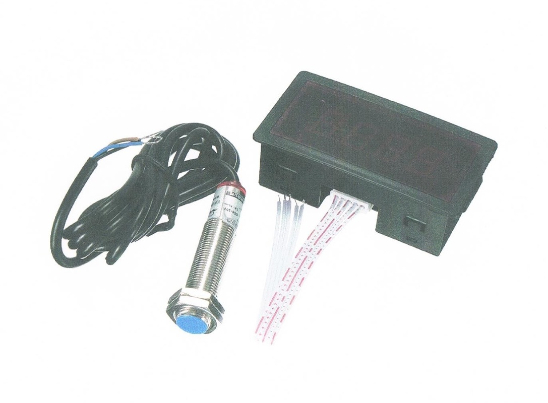
The digital tachometer was from China and the cost was around £6 which was less than I paid for the original cycle computer tachometer. It came complete with a hall effect sensor and a magnet.
My first idea was to recess the magnet into the flywheel and mount the sensor underneath. However, when the unit arrived it was obvious that the sensor was far to large to fit in this way. I made some tests on the sensor and discovered that it provided a negative pulse when activated by the magnet. |
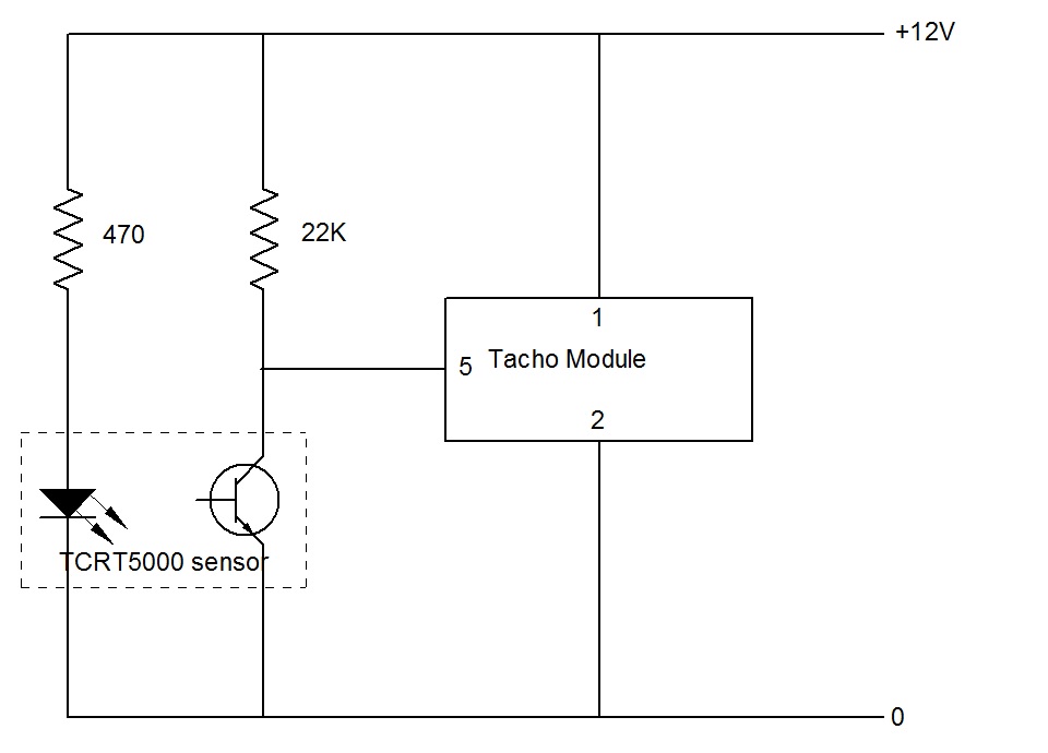
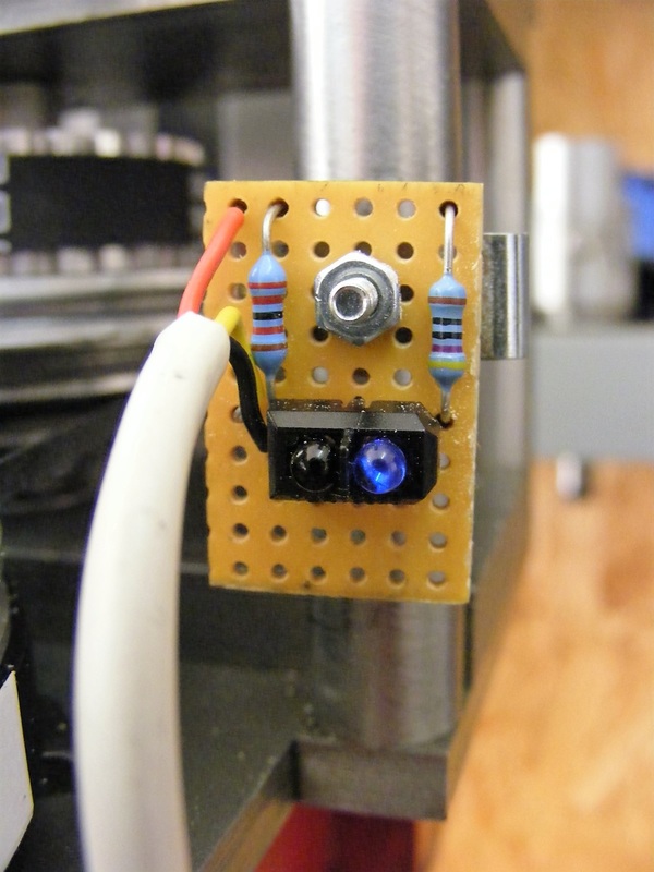
I decided to scrap the Hall effect sensor and instead fit a reflective strip to the edge of the flywheel and then use a reflective optical sensor to trigger the tachometer. The circuit to do this is very simple as shown below.
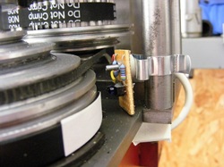
This shows the sensor module mounted on a small terry clip that attaches to the frame of the belt drive assembly.
Note the black disc beneath the stepped pulley. This is the new flywheel.
Also note the strip of white label attached to the flywheel. This is the reflective strip sensed by the TCRT 5000 sensor.
Note the black disc beneath the stepped pulley. This is the new flywheel.
Also note the strip of white label attached to the flywheel. This is the reflective strip sensed by the TCRT 5000 sensor.
|
This is a close up of the sensor. The IR diode is on the right hand side of the sensor and the phototransistor is on the left hand side.
The circuit board is connected to the tachometer module with a three core cable. |
|
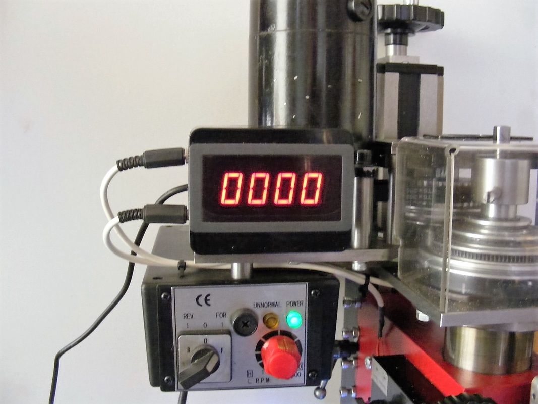
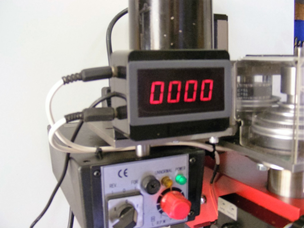
The tachometer module is housed in a small ABS enclosure. All the connections are on the left hand side of the box.
The unit is supplied with 12 V DC from a plug in 1 amp power supply. The sensor is connected via the stereo jack plug at the top of the box. The lower jack plug is a 12 V DC outlet that supplies the ring light around the spindle. |
The new tachometer is much easier to read than the old cycle computer and it avoids the use of multiplication factors.
