Moving steady
After making the tee slot cross-slide the standard Sieg steady would no longer fit. This was because the new cross-slide was wider than the standard cross-slide. I did a quick fix to solve this problem by bolting the old moving steady to a bar that then mounted on the side of the carriage. Harold Hall in the January 2011 issue of Model Engineers' Workshop presented some designs of fixed and moving steadies for the Myford lathe and this inspired me to make a new mobile steady. My construction technique for the new moving steady differs greatly from that proposed by Harold Hall. I believe my method is much simpler and more economical with material.
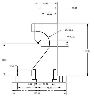
This is a drawing showing the dimensions of the steady. The upper part is made from a piece of 12x50 mm flat steel. The base is a piece of 12 x 19 mm flat steel. The two parts are bolted together with two M5 screws through the base.
First the upper part was cut to size and the ends were milled flat. The steel was then marked out for the centre of the circular arc. A hole was made at this centre using a 46 mm holesaw. Since the hole overlapped the edge there was no problem with clearance of the swarf produced by the sawing operation. The rest of the metal to be removed was sawn off using the bandsaw. The piece was then cleaned up by filing.
The base was then prepared by cutting to length and drilling the two 6 mm holes that mount the steady to the carriage. This was then bolted to the top part.
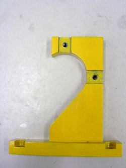
Two recesses were cut in the top part. These were 12 mm wide and 3 mm deep. This recesses are for the fingers that support the work.
Note the two holes in the base have been counterbored for M6 socket head screws. These counterbores broke slightly out of the side of the base so the counterbore were extended out to the side using a 10 mm endmill.
Each recess has a M5 hole drilled in the centre. These are for the finger locking screws.
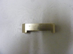
The steady fingers were made from 12 mm square brass. A recess is milled in the bottom 3 mm deep. Note that the two ends are not identical.
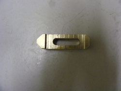
The left hand end is longer and reduces to a 4 mm flat at the tip whilst the right hand end is shorter and reduces to an 8 mm tip. The left hand tip is used to support small diameter work whilst the right hand end is designed for larger diameter work.
The fingers are slotted along the length. These slots are for the fixing screws.
The fingers are slotted along the length. These slots are for the fixing screws.
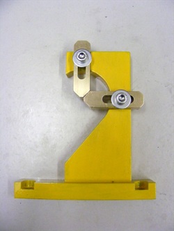
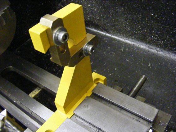
The fingers fit into the recesses in the steady as shown here. The fingers can slide in the slots but can be locked into position by the two M5 socket head screws.
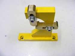
The finished steady.
