Swing up toolholder for threading.
I normally single point thread on the lathe keeping the half nut closed during the entire operation. In single point threading of a right hand thread the carriage moves towards the headstock. During cutting the forces acting on the tool are downwards and from the right. At the end of each cutting pass the normal procedure is to withdraw the tool with the cross-slide, move the carriage back to the start of the thread and then reset the depth of cut to make the next pass. Failure to withdraw the tool normally results in the tool tip breaking. All this withdrawing and resetting the depth is tedious and time consuming. What is really needed is a tool that will be rigid to the forces that act during cutting but flexible when the forces act in the other directions when returning the carriage to the start of the thread. If this could be achieved then there would be no need to withdraw the tool when returning the carriage.
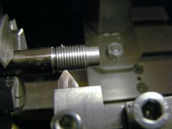
I visualised a tool on a pivot allowing it to swing up and down, but with a stop beneath it so that it could not swing below the horizontal. To test this concept out I made the prototype shown here. This consisted of a block mounted on the toolpost. Attached to the block was a swinging arm which formed the toolholder. The front of the tool rested on a plate attached to the block. During cutting the plate resisted any downward force on the tool and any force from the head stock side pressed the toolholder arm against the rigid mounting block. Trials with this swing up toolholder were very encouraging. Keeping the half nut closed throughout the procedure it was possible to advance the tool, make a cut, reverse the lathe motor to take the tool back beyond the start of the thread, increment the cut a little and then make the next pass. On the reverse traverse, with the spindle running in reverse, the tool could not cut, and was lifted by the part formed thread. When the tool tip ran off the end of the thread it just dropped back in position. This was so simple compared with the normal threading procedure and much less prone to error.
The idea was taken a little further by "Bogstandard" on the Madmodder website (http://madmodder.net/index.php?topic=2323.0) to make a tool that would cut either right or left hand threads. This tool worked very well. Several people have now made versions of the swing up tool and all report very favourable results.
The swing up tool described here is very much based on the construction sketch given by "Bogstandard" in his concluding remarks.
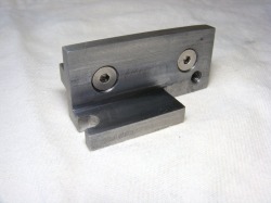
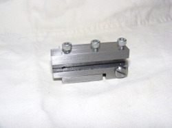
This photo shows the base of the toolholder. This was cut from a piece of 25 mm x 5mm bright steel angle. The two countersunk screws attach a piece of square bar to the back of the unit that is used to mount the tool in a normal toolholder. The M5 threaded hole on the right hand side is for the pivot pin. The cut out in the bottom horizontal part of the base is for pin that locates the swinging arm.
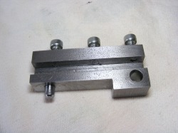
This is the swinging arm. This is made from a piece of 25 mm x 12 mm steel bar. The slot is to accommodate the tool and the clamping screws can be seen at the top. This slot goes right through the bar so there is no need to cut the length of the tool to any particular size. The cut out accommodates the base support plate. The hole on the right is for the pivot pin. Note the locating pin on the bottom right of the arm. This locates in the slot in the base plate.
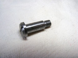
The pivot pin is shown here. It is 6 mm diameter with an M5 threaded tip. It was machined from a piece of 12 mm round bar. The swinging arm must pivot freely on the pin and the unthreaded length must be such that when the arm is screwed to the base there is a slight clearance so that it swings freely.
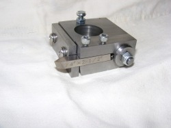
This shows the assembled swing up toolholder. The toolholder is straight forward to construct but care should be taken to ensure that the swinging arm swings freely without too much play and that the locating pin is an accurate fit in the slot in the base. Because the pivot is so far back and the locating pin is right up near the tip of the tool then any play due to the pivot is reduced at the tool tip. To get a good fit for the locating pin in the slot in the base the tool was made and assembled without either of these features. With the arm and base firmly clamped together a 4 mm hole was drilled through the base and into swinging arm and into the tool slot. A steel pin was then made that was a force fit in the hole in the swinging arm. Then a slot was cut in the base to meet the hole using a hacksaw. The slot was then slowly enlarged with a needle file until the pin was a smooth gliding fit into the slot when the swinging arm was lowered.
Here the toolholder is shown folded right back. It is possible to use the swing up toolholder with the classic method of thread cutting where at the end of each cutting pass the tool is returned to the start by disengaging the half nuts and winding the carriage back. In this case at the end of each cutting pass the tool is simply lifted up and folded right back. After releasing the half nuts and winding the carriage back, the tool is then folded forward again for the next cutting pass, after incrementing the cut a little.
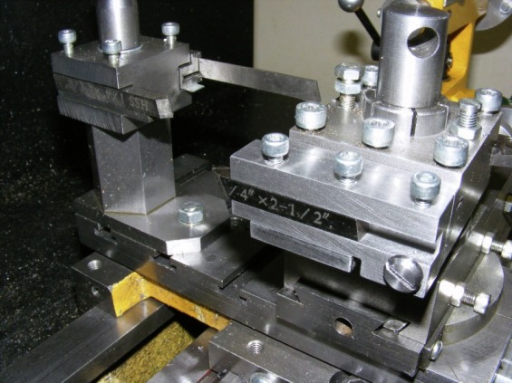
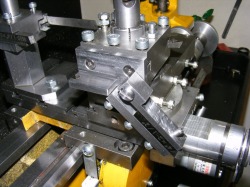
This photo shows the swing up toolholder in use. This toolholder is a delight to use and it greatly speeds up and simplifies single point thread cutting. This is especially so when used in conjunction with the lathe motor autostop. The tool is suitable for both right and left hand external threading. There are some good videos of a swing up toolholder in action on the Madmodder website.
