Tachometer
When I first had my lathe I fitted a very simple tachometer based on a readily available cycle computer, see here. Since that time I have fitted a 60 position index wheel. More recently I came across a cheap digital frequency meter, item number 350855663428, on ebay being sold by a company called "sureelectronics". The price of this unit from China was £5.56. It has a LED display with 0.56" characters.
One revolution of the lathe spindle means that the 60 holes on the indexing wheel pass a fixed point on the lathe. If these holes could be detected and converted to an electrical signal then 1 rpm would give 60 pulses per minute which equals 1 pulse per second or 1 hz. Thus a frequency meter counting the pulses will directly record the revolutions per minute.
One revolution of the lathe spindle means that the 60 holes on the indexing wheel pass a fixed point on the lathe. If these holes could be detected and converted to an electrical signal then 1 rpm would give 60 pulses per minute which equals 1 pulse per second or 1 hz. Thus a frequency meter counting the pulses will directly record the revolutions per minute.
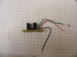
I had several of these optical sensors that I had salvaged from old inkjet printers. On one side of the gap is an infra-red emitting diode and on the other side is a phototransitor. If something blocks the gap then the infra-red beam is interupted and the phototransistor responds,
Note there are only three wires going to the sensor. One goes to the infra-red diode (red wire) and one to the transistor collector (green wire). The black wire it a common ground for both devices.
Note there are only three wires going to the sensor. One goes to the infra-red diode (red wire) and one to the transistor collector (green wire). The black wire it a common ground for both devices.
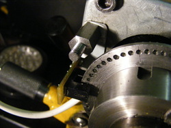
This photo shows the sensor mounted so that the 60 position index wheel runs in the gap. The sensor is screwed to a steel bracket that fixes under the hexagonal spacer.
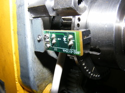
This is view of the back of the sensor board and the steel bracket.
The white lead connects to the sensor board and it terminates in a stereo jack plug.
The white lead connects to the sensor board and it terminates in a stereo jack plug.
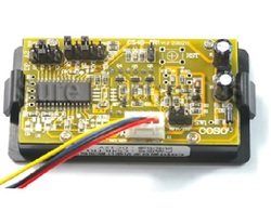
The frequency meter connections are via the plug at the bottom of this photo. At the top of the board are a number of jumpers that allow the board to be programmed to act as a frequency meter or a counter.
The meter needs 12V dc to operate. This is connected to the red and black leads on the plug. The signal from the sensor goes to the yellow lead and the blue lead is connected to ground.
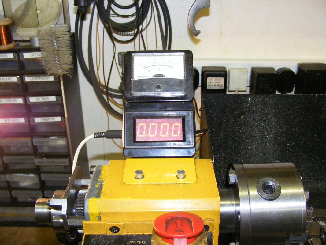
The frequency meter was mounted in a small ABS plastic box and attached to a bracket mounted on the headstock, as shown on the header photo. The sensor jack plug connects to a jack socket on the side of the ABS box.
Above the frequency meter is mounted an ammeter that measures the lathe motor current.
The meter needs 12V dc to operate. This is connected to the red and black leads on the plug. The signal from the sensor goes to the yellow lead and the blue lead is connected to ground.
The frequency meter was mounted in a small ABS plastic box and attached to a bracket mounted on the headstock, as shown on the header photo. The sensor jack plug connects to a jack socket on the side of the ABS box.
Above the frequency meter is mounted an ammeter that measures the lathe motor current.
The Circuit
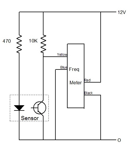
The circuit is very straightforward. The infra red diode is fed via a 470 ohm resistor and a 10 K resistor is used as a collector load. The collector is connected directly to the frequency meter as shown.
The new tachometer works very well. It does no more than my old cycle computer tachometer but it is much easier to read. The cost is actually less than that of the old cycle computer but it does require the 60 hole disc, or similar interupter, in order to function.
The new tachometer works very well. It does no more than my old cycle computer tachometer but it is much easier to read. The cost is actually less than that of the old cycle computer but it does require the 60 hole disc, or similar interupter, in order to function.
