Toolpost drill
This project started because I wanted to make some dividing plates for the headstock indexing attachment. The ideal arrangement for this would be some sort of toolpost drill. I had read a number of articles where a Dremel type unit had been attached to the toolpost either directly or via a flexible drive. The problem with this type of unit is that these units run very fast and are only suitable for drilling the smallest of holes. A second problem is that they do not accommodate an accurate chuck. The third problem with the flexible drive shafts is that the bearing seem to have much side play and they do not seem to be suitable for accurate drilling and they are not really designed to transmit much power. To overcome these problems I started to look at flexible drive systems that could be attached to a normal electric drill. These seemed to be much more suitable since they were supplied with a 6 mm chuck and were obviously designed to transmit much more power.
The flexible drive
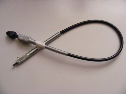
The flexible drive was purchased from Screwfix. They have since discontinued the item but an identical unit is available from Toolstation. The drive is solidly made with substantial diecastings, with grease nipples, at the two ends. Initial inspection showed that the supplied chuck was a very simple affair with suspect accuracy, and there was considerable end play and side play in the chuck shaft bearing. The chuck shaft could be easily unscrewed and it was just a plain shaft runniing in the diecast end of the drive. The end of the shaft was threaded M6 and this screwed into the end of the drive shaft. The first job was to find a way of mounting the drive onto the toolpost. This was straightforward. A slot was milled along the chuck end diecasting and a piece of 6 mm plate then screwed to the diecasting.
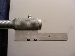
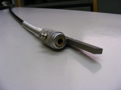
This photo shows the plate attached to the diecasting using M3 socket head screws. The shape of the plate allows the end to be mounted on the toolpost for either axial or radial drilling. The small hole in the plate is just to enable the tool to be hung up on a pin when not in use.
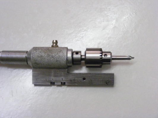
This photo shows the drill set up in a toolholder for radial drilling. The toolholder can be turned through 90 degrees for axial drilling. The chuck in this photo is the one supplied with the flexible drive. The run out on the chuck was considerable and this and the side play on the chuck shaft made accurate drilling impossible.
Improving the bearing.
Having found a method of mounting the drive shaft the next job was to improve the bearing. The end diecasting was chucked in the lathe with the rest of the flexible drive supported in a length of 20 mm tube that passed into the spindle from the rear of the headstock. The diecasting was drilled out to 12 mm. A phosphor bronze bush with a 6.7 mm bore was then made that was a tight fit in the diecasting. The length of the bush, 26 mm, was such that circa 1 mm would protrude from the end of the diecasting to provide a thrust surface. A new shaft, 64 mm in length, was made that was a good sliding fit in the bore. The end was threaded using an M6 die to screw into the drive shaft. A collar was also made for this shaft to take the thrust from the chuck. The bush was pressed into the diecasting and a hole drilled for the grease nipple. The shaft was then screwed onto the drive shaft. The collar was adjusted to give a slight end play. and then pinned into position with a 3 mm pin.
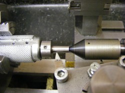
A new chuck was purchased from Arc Eurotrade. This is shown in the header photo and is a 0.4-4 mm chuck with a JT0 taper. The next step was to cut the taper on the shaft so that it would accept the chuck. The topslide was set over to the correct angle for a JT0 taper. This was difficult because I had no male JT0 taper as a reference. However, using a trial and error approach on scrap material I eventually arrived at a taper angle that fitted the chuck well. The drive shaft was then set up in the lathe chuck as shown in the photo. This shows the drive shaft and the collar attached to the chuck shaft. The drive shaft was attached to an electric drill and this was used to rotate the shaft. The JT0 taper was then cut. Cutting the taper in this way ensures that the taper is coaxial with the shaft.
Using the attachment.
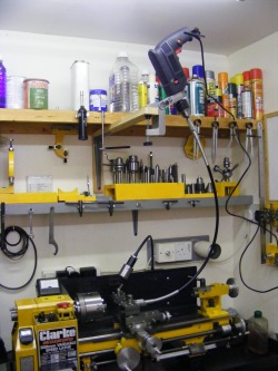
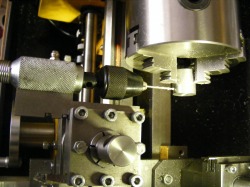
This photo shows the attachment in use on the lathe. By mounting the drill above the lathe as shown the carriage can swing the whole length of the lathe. The electric drill is a cheap variable speed drill from Argos, and it is clamped to the horizontal beam using a commercial drill clamp. The attachment is very quick and easy to set up and it has been found to be very accurate
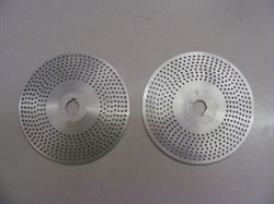
This photo shows a pair of division plates made using the toolpost drill in conjunction with the headstock indexing attachment. The plates are aluminium and the hole size 2 mm. The attachment will drill 4 mm holes in steel without any problem.
