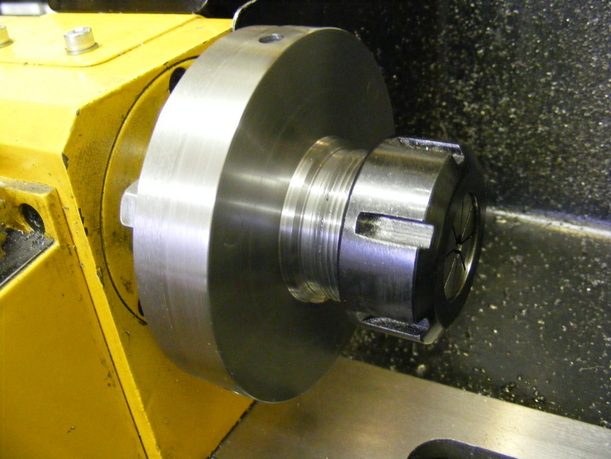
ER32 chuck for 100 mm spindle
I had previously made an ER32 chuck for the standard 80 mm spindle (see here). This no longer fitted after upgrading the lathe spindle (see here). The ER32 collet chuck described here was designed to fit the new spindle. The construction is slightly different from the previous version in that a thicker flange has been used. This enables the holes for the tommy bar to be placed in the flange. The chuck is designed with only three mounting studs.
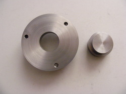
The flange was made from a piece of 1/2" hot rolled steel plate. This was marked out with a centre, a 100 mm circle and for the 3 mounting studs. The plate was then roughly trimmed slightly oversize using the bandsaw. The holes for the three mounting studs were then drilled and tapped M8. Three 30 mm studs were cut to fit these holes from M8 studding. The flange was then mounted on the spindle using three M8 nuts, carefully selected to be the same thickness, as spacers. The edge of the disc was then machined to a true circle but still leaving it oversize. The disc was faced to clean off all the oxide. A hole was drilled through the centre of the disc and this was bored out to 35 mm diameter.
The hub was made from a 35 mm length of 45 mm round EN1A bar. A shoulder, to fit in the hole in the flange. was machined for a length of 1/2". The hub should be an easy fit in the flange.
The hub was then silver soldered into the flange. The mating parts were liberally coated in Easyflo flux. and some small pieces of silver solder cut off and placed between the shoulder and the flange. The whole thing was then heated up until the solder ran into the joint. I heated the assembly in my furnace.
After cooling the assembly was remounted on the spindle flange using the three nuts as spacers. The hub was then remachined to remove the oxide coating and to get the hub concentric with the axis of rotation.
The assembly was then dismounted from the spindle and the three jaw chuck mounted. The hub was firmly gripped in the three jaw chuck and the back of the flange faced to a good finish. The central recess was then cut using a boring tool. This should be 4 mm deep and 72 mm diameter. I bored in out to 71 mm diameter at first and then used a very sharp knife tool to cut the recess to its final diameter. I used the old 80 mm-100 mm chuck adaptor plate to test the recess as I approached the final diameter.
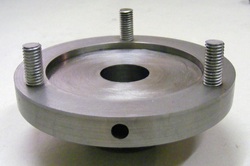
The back of the flange after machining.
The hole in the edge of the flange is for the tommy bar. There are three such holes on the circumference spaced midway between the studs.
The recess should be an exact fit onto the spindle flange.
The hole in the edge of the flange is for the tommy bar. There are three such holes on the circumference spaced midway between the studs.
The recess should be an exact fit onto the spindle flange.
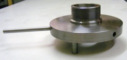
The assemby was mounted onto the spindle flange with the studs slightly protruding through the front face. The studs were held in position with a little Loctite on the threads. The flange face and studs were machined flat and the hub remachined to a good finish. The edge of the flange was machined down to 100 mm diameter and chamfered. The hub was drilled and then bored out to 20 mm diameter. The hub was turned down to 40 mm for 20 mm and a run out groove cut circa 5 mm wide and 0.8 mm deep in preparation for threading. The hub was then single point screw cut with a 1.5 mm pitch thread to fit the ER32 cap nut.
The final operation was to cut the taper for the ER32 collets. I mounted an MT2-ER32 collet chuck in the spindle using an MT2-MT3 adaptor and then set the top slide over at an angle to match the taper in the chuck using a DTI to ensure accuracy. Once this was done the flange was remounted on the spindle and the taper was cut using a boring tool.
The finished chuck is shown in the header photo.
The finished chuck is shown in the header photo.
